From Raspberry Pi to Smart Home: My First IoT Project
Raspberry Pi, Node.js, coffee with a click and SBB connections: a look back at my 2016 home automation system, its architecture and lessons from my first IoT project.
- Raspberry Pi
- Node.js
- Socket.IO
- IoT
- Home Automation
- Retrospective
Engineering Journal · Looking back at 2016
One click in a browser, and a light turns on at home or the coffee machine starts: that was the idea behind my first IoT project. In 2016, I connected Raspberry Pi, Node.js and Socket.IO to build my own home automation system. This is a look back at that setup, with original images, improvised solutions and what I would approach differently today.
A new apartment, my own home automation system
I had just moved into a new apartment and wanted to find out how to connect everyday devices with my own software. Rather than control individual devices in isolation, I wanted a shared interface for my home.
The options were C# and a web stack. I chose Node.js because I wanted to build a web application with real-time communication. Express served the interface, while Socket.IO carried events between the browser and server.
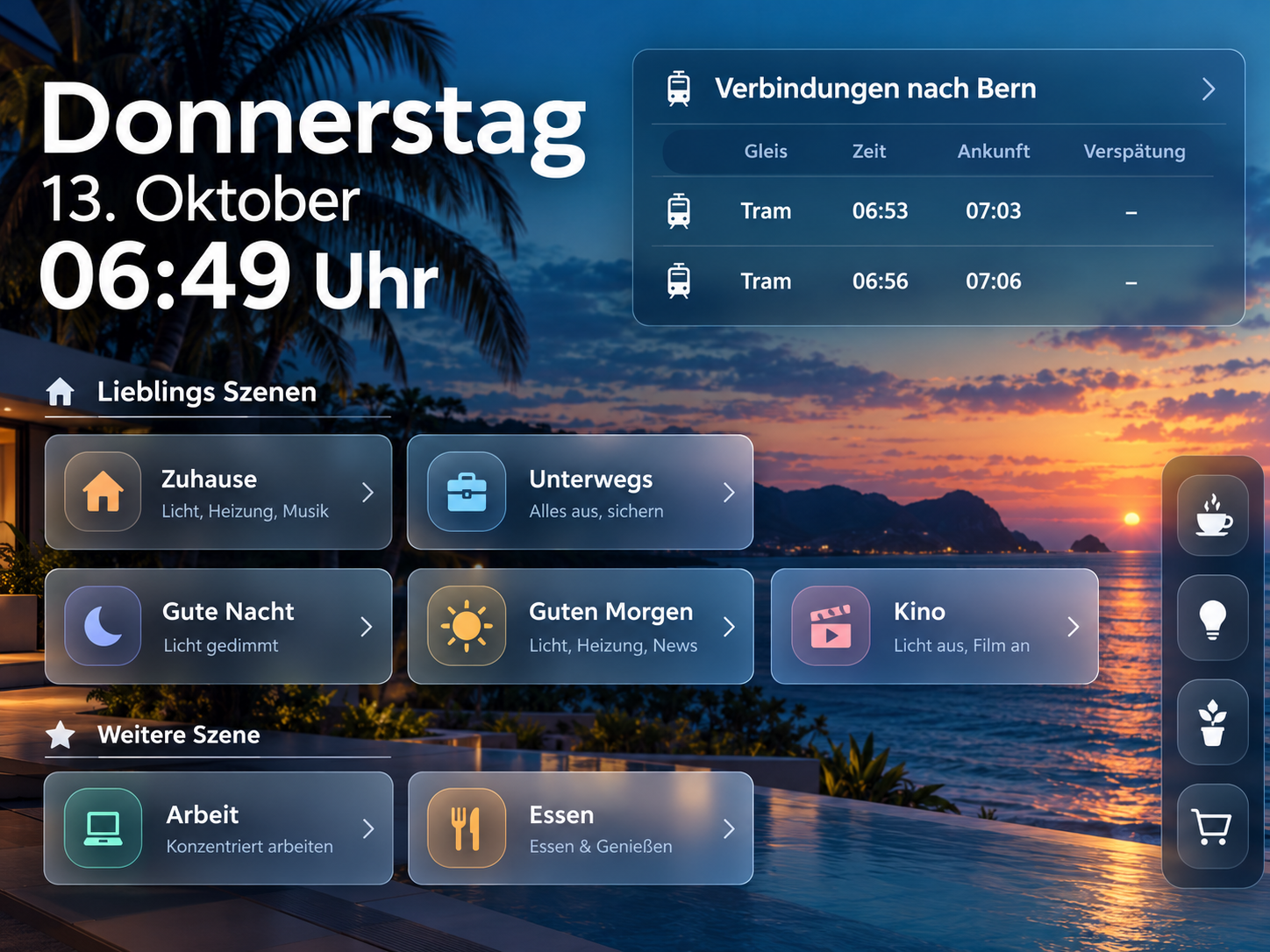
The dashboard displayed the time, weather and the next connections to Bern. Its background also changed with the time of day. I wanted the interface to be useful in the morning as well as when turning off the lights at night.
The dashboard illustration was created for this retrospective.
Lights and scenes in one interface
The interface brought together scenes such as “At home”, “Away”, “Good night” and “Cinema”. I wanted frequent routines to be accessible with a few clicks and several devices to share the same control interface.
The Hue lights were a concrete part of this lighting setup. Motion, temperature and light sensors, along with plant watering, belonged to the planned extensions.
Philips Hue: controlling lights through the bridge
For my Hue lights, I used the Hue Bridge and the Node.js package node-hue-api. The server sent lighting commands directly to the bridge on the local network. Its IP address and API access value were hard-coded in the original example.
A switch in the browser triggered a Socket.IO event. LightOben controlled a single light, while LightAll switched the three connected lights together. Node.js applied the requested state through api.setLightState(...) and broadcast events such as LightObenTrue or LightAllFalse to the connected browsers. JavaScript then updated their switches.
Browser → Socket.IO → Node.js → Hue Bridge → Lights
Node.js → Socket.IO → Switches in the connected browsers
The DayNight routine switched off the first light immediately, the second after five seconds and the third after ten seconds. A single click triggered a small timed sequence.
Looking back, the feedback had an important limitation: the socket events updated the interface without confirming the actual state of each light. Today, I would distinguish commands, successful bridge responses and observed light states. For a reliable smart home, the interface and the device state need to agree.
SBB connections directly on the dashboard
For me, a smart home also included the question: when does my next connection leave? I added a timetable display for Bern Europaplatz → Bern. Alongside the time and weather, the information for leaving home appeared in the same interface as the device controls.
The data came from the open Swiss public transport API at transport.opendata.ch. I called the integration “SBB” in my code; the requests used this open API. The display showed the next four connections with platform, departure time and arrival time.
The original data flow had a detour of its own: the browser fetched the JSON response using $.getJSON and sent the entire connections object to Node.js as a Socket.IO event named SBB. The server extracted individual values and returned them through events such as SBBZEIT0, SBBGLEIS0 and SBBANKUNFT0. The browser inserted them into the corresponding table cells.
Public transport API → Browser → Socket.IO → Node.js
Node.js → Socket.IO → Timetable in the browser
The limitations of that example are interesting too: the “Delay” column was already present, but the published code did not populate it yet. I replaced an empty platform field with “Tram” as a blanket fallback. Today, I would derive transport modes and delays from the appropriate data fields, explicitly handle missing information and display the time of the last update.
This integration turned a remote control for the apartment into a dashboard that also helped plan the next journey.
How the browser and devices communicated
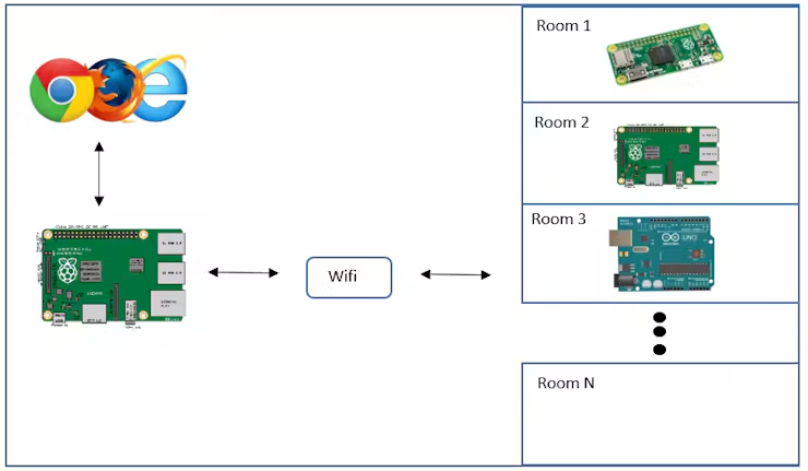
A central Raspberry Pi was intended to host the web application. Additional Raspberry Pis or Arduinos were planned as device and room controllers. My hardware list included a Raspberry Pi 2, a Pi Zero and 5V relays.
The Raspberry Pi device controllers ran small web servers. Fixed IP addresses and PHP endpoints such as espresso.php or Doppio.php mapped a request to an action. The PHP file launched a script that operated the GPIO pins and relays. Hue used a separate path through the bridge API.
The unusual part sat between these components: I did not yet know how to send an HTTP request directly from Node.js to another device. So Node.js wrote a GPIO value. A separate script checked the pins in a loop and triggered the corresponding curl request.
It was a detour, but it captures where I was in my learning: combining the tools I already understood to make the next connection in the system work.
The original architecture diagram shows the planned relationship between the central controller and the device controllers.
The concept behind the extensions
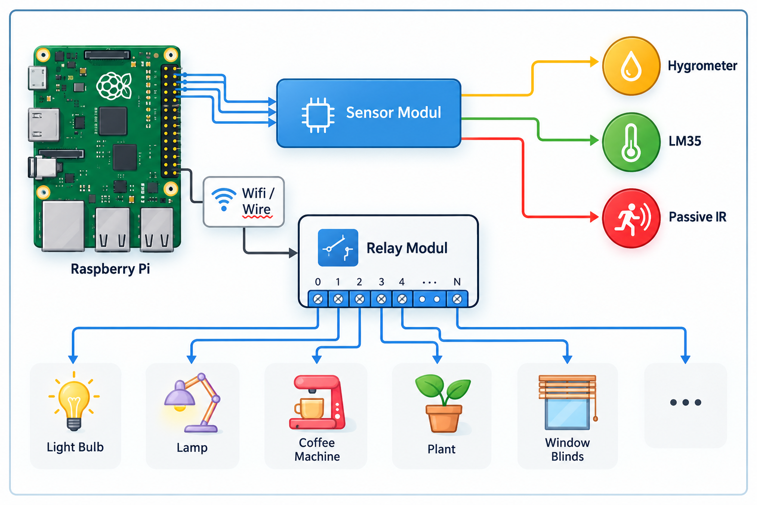
This additional concept illustration shows the idea behind the system: a Raspberry Pi connects sensors and relays to everyday devices. Humidity, temperature and motion represent the planned sensors; lights, the coffee machine, plant watering and blinds represent possible applications.
The illustration explains the concept, including extensions that were not yet fully implemented at the time.
The most tangible result: coffee with a click
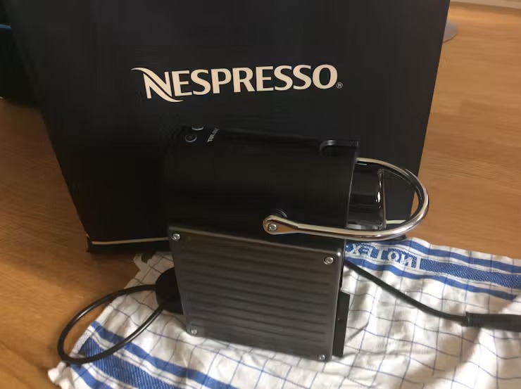
For the coffee machine, I used a Nespresso Pixie. Relays took over the button presses, and a Bash script controlled the sequence: switch on, warm up, trigger brewing and switch off at the end.
In the original doppio script, the machine first waited for 34 seconds. Switching intervals of 11.5, 10 and 10.9 seconds followed, separated by short pauses. These fixed timings turned a browser command into a physical sequence on a real device.
This made the distinction between software state and reality particularly clear: sending a command does not confirm that the machine is ready or that the coffee has actually finished brewing. Today, I would model this sequence with state feedback and explicit failure cases.
The Nespresso Pixie from my original project, photographed before the modification.
The modification: from the housing to the buttons
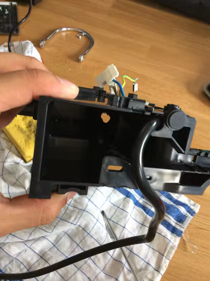
The slider documents three steps on the device: the opened housing, the button board with the added jumper wires and the internal cable routing. This connection allowed the external controller to integrate the existing buttons into the programmed sequence.
The mechanical work was as much a part of the project as the script: opening the housing, reaching the controls and routing the additional wires out of the machine.
Original photos from 2016: housing → button board → internal view. Use the arrows to move between the three images.
Relays and wiring on the prototype
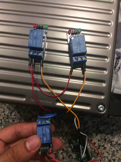
Three wired relay modules and the Raspberry Pi below show the connection between software and device. The script defined the sequence, while the relays operated the switching contacts. The second photo shows a close-up of the circuit board underside and connected wires.
These photos make visible what an architecture diagram can only represent as a line: between the browser command and the finished coffee were wires, contacts and a timed control sequence.
Original photos from 2016: relay overview → circuit board underside. Both photos are available in the slider.
What I would approach differently today
Direct communication. I would replace the GPIO detour with direct HTTP requests or communication through MQTT. Commands and feedback should be clearly separated.
Confirmed states. A dashboard should distinguish between an action being requested, completed or failed. Timeouts, lost connections and temporarily unavailable devices are part of the process.
Access and configuration. The published examples contained fixed IP addresses and a Hue access value in the code. Today, I would keep configuration and credentials separate and deliberately secure access to the interface and devices.
A shared device model. Instead of many similar socket handlers, I would describe devices, actions and states consistently. New devices could then be added through configuration without repeatedly copying the same code.
What stayed with me
I was drawn to the idea that a line of code could trigger something outside the screen. At the same time, I had to deal with timing, Wi-Fi connections and processes that could not simply be reset by refreshing a page.
Today, I see this as an early step towards understanding systems as connected processes: the interface, communication, device and feedback all have to work together. That is why this project is worth revisiting for me, including the detours in the original code.
The original architecture diagram and hardware photos come from my 2016 project documentation. The newly designed illustrations complement this retrospective.